Comparison of single beam trap and standing wave trap
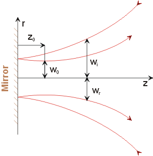
Here we compare the properties of optical traps created in the single focused Gaussian beam and in the Gaussian standing wave genereated by retroreflected Gaussina beam on a 100% reflective mirror. We assume here that the positive direction of the z-axis follows the propagation of the reflected beam and it is antiparallel to the direction of the incident beam. Therefore, positive axial force acts against the incident beam propagation.
 |
|
w0,
wi, and wr are the radius
of the Gaussian beam waist, radius of the incoming and reflected wave
at certain axial position z. z0 is the distance
of the beam waist from the mirror. Positive (negative) z0
means that tha beam waist is created in the reflected (incident) beam.
|
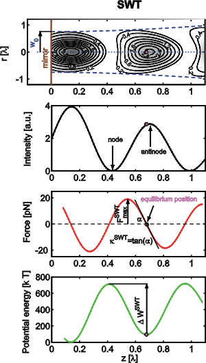
Situation in the standing wave trap (SWT) and single beam trap (SBT) and definition of studied parameters
The following figures illustrate the differences between intensities, axial forces, and trapping potentials of both types of traps. These plots also define the maximal axial trapping force Fmax, axial trap stiffness k, and potential depth of the trap DW.
 |
 |
Comparison of maximal traping forces
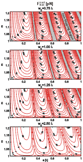
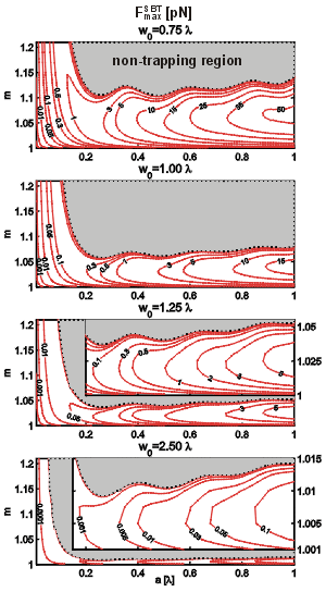
The contour plots of the maximal trapping force values have been chosen as the most comprehensive way to show the principal force dependencies on the particle radius a, relative refractive index m=ni/ne, and beam waist size w0. The contour labels represent levels of constant forces in pN, the shaded regions correspond to the negative maximal trapping force (non-trapping regions). For these parametric configurations the particle is accelerated in the incident beam direction without a chance of its confinement. In the GSW the width of the non-trapping regions increases with particle size. It is also seen that the shaded regions are getting narrower with increasing beam waist since the gradient of the intensity of the Gaussian envelope becomes smaller.
It is interesting to compare maximal axial trapping forces in the SWT and in the SBT for the same particle sizes, relative refractive indices, and beam waists. It is seen immediately that the wider is the beam waist, the narrower is the region of relative refractive indices where the particle can be confined using SBT and this region reduces to the unity value of the relative refractive index for bigger particles. This means that using wider beams, only those objects can be trapped by SBT which have the refractive index close to the value of surrounding immersion medium. If the values of maximal trapping forces for bigger particles are compared, one finds that the SWT provides at least one order of magnitude stronger trapping forces. For smaller particles and wider beam waists (outside the non-trapping regions) this disproportion becomes even more pronounced.
 |
 |
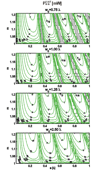
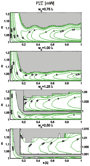
Comparison of minimal trapping powers
Due to the competition of the scattering and gradient forces, the total axial force is the most limiting factor of the optical confinement. The stability of the trap along the optical axis can be inferred from the axial profile of the potential energy. As only on-axis sphere position is assumed here, the change of the potential energy due to the motion of the sphere in the field from the starting position z1 to the end position z2 is given by:

Here, F(z) is the axial optical force calculated by the GLMT and acting on the sphere placed at z. The integration of the GLMT force along the z axis gives potential energy profile whose minimum represents the equilibrium position of the sphere in the trap.
The knowledge of the trap depth can be employed to obtain minimal trapping power that is necessary for axial confinement of a particle. It is generally accepted that if the trap is deeper than 10 kB T (kB is the Boltzmann constant and T the absolute temperature), the particle can be considered confined. We defined the trap depth as the difference between the potential energy of the lowest trap edge and the trap bottom (see above). The power that provides the trap depth equal to 10 kB T will be called the minimal trapping power. The minimal trapping power was calculated as a function of sphere radius a, relative refractive index m, and beam waist size w0. The contour line labels give the minimal trapping power in mW. The shaded areas correspond again to the "non-trapping" configuration of parameters.
The plots reveal that the minimal trapping power in the SWT can be smaller than 1 mW even for w0=1.25 l if optimal sphere size and slightly higher relative refractive index are chosen. In contrast, much higher trapping power must be used to confine smaller spheres or spheres close to the non-trapping radii. Quantitative comparison of the SBT and SWT shows that for the same relative refractive indices, the SWT needs lower trapping powers for spheres smaller than about one half of the trapping wavelength. Bigger spheres are influenced by neighbouring antinodes which tend to pull the sphere to opposite sides and decrease the total axial trapping force. Thus, the trap gets shallower. It is also seen that the differences between the minimal trapping power needed in the SWT and in the SBT are not as big as the differences in maximal trapping forces. This is caused by the fact that - unlike the trapping force - the trap depth does not depend on the intensity gradient but rather on the difference between the maximal and minimal intensity, which is comparable in both cases.
The maximal SWT optical force induced by the minimal trapping power is still 10 times bigger than the total force produced by the gravity and buoyancy force. Therefore, the SWT axial position can be considered as unaffected by these forces, which is not the case if the SBT with minimal trapping power is used.
 |
 |
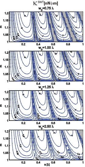
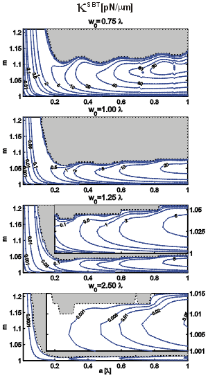
Comparison of trap stiffnesses
The knowledge of the trap position enables estimation of the trap stiffness. It is assumed that for small deviations of the trapped particle from its equilibrium position the restoring force is linearly dependent on this deviation and the proportionality constant defines the trap stiffness (see above). The stiffness was obtained as the derivative F(z) with respect to the z co-ordinate at the trap position. Comparison of the stiffnesses of the SWT and the SBT for such sphere radii and refractive indices where the maximal trapping force is significantly higher that the total force produced by gravity and buoyancy reveals that the stiffness produced by the SWT is at least by two orders of magnitude bigger (the units used for the contour labels of the SBT stiffness are in pN/mm but those for the SWT in nN /mm). Therefore, the particles in the SWT are more precisely confined axially. Non-trapping regions are shaded, except the upper left corner where the trap positions were not analysed.
 |
 |
Conclusions
To summarise, we proved theoretically that the SWT enables dielectric sphere confinement in a wider range of sphere refractive indices and beam waists compared to the SBT. Apart from small regions of the sphere sizes and refractive indices, where the GSW effect is cancelled, the force, stiffness, and depth of the SWT for comparable parameters of the sphere and the laser beam are generally bigger than corresponding properties of the SBT.
Related publications
P. Zemanek, A. Jonas, P. Jakl, J.
Jezek, M. Sery, M. Liska: "Theoretical comparison of optical
traps created by standing wave and single beam",
Opt.
Comm. 220, 401-412, 2003,
ABSTRACT DOWNLOAD
P. Zemanek, A. Jonas, M. Liska:
"Simplified description of optical forces acting on a
nanoparticle in the Gaussian standing wave",
JOSA A 19, 1025-1034, 2002,
ABSTRACT DOWNLOAD
P. Zemanek, A. Jonas, L. Sramek,
M. Liska, : "Optical
Trapping of Rayleigh Particles Using Gaussian Standing Wave.",
Optics Communications,
151, 273-285, 1998. ABSTRACT DOWNLOAD
Send comments to webmaster
Last modification: 30 Mar 2007

